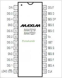
Basically, 8x8 LED matrix work mainly with the help of an Max7219 IC. This 24 pin IC is capable of handling an 8x8 led matrix.
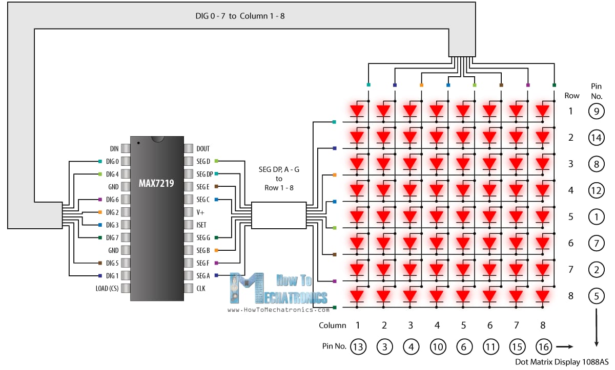
The MAX7219 is a compact, serial input/output common-cathode display driver that can interface microprocessors to 7-segment numeric LED displays of up to 8 digits, bar-graph displays, or 64 individual LEDs. Included on-chip are a BCD code-B decoder, multiplex scan circuitry, segment and digit drivers, and an 8x8 static RAM that stores each digit. This IC is 24 pin IC, 12 on each side. 16 pin is used for connecting it to the matrix. 2 pin is dedicated to ground and one is dedicated for VCC. Data from microcontroller is entered to the MAX7219 through DIN pin while another is connected to shift data from one module to another through DOUT pin. One pin is dedicated for Clock. Pin 12 is for chip select (CS) which determines number of modules connected together while programming of the project.
| Rows corresponding to pins of Matrix | Connection with MAX7219 CNG & pin number of IC |
|---|---|
| Row 1, Pin 9 | SEG DP, PIN 15 |
| Row 2, Pin 14 | SEG A, PIN 23 |
| Row 3, Pin 8 | SEG B, PIN 21 |
| Row 4, Pin 12 | SEG C, PIN 17 |
| Row 5, Pin 1 | SEG D, PIN 14 |
| Row 6, Pin 7 | SEG E, PIN 16 |
| Row 7, Pin 2 | SEG F, PIN 22 |
| Row 8, Pin 5 | SEG G, PIN 20 |
| Columns corresponding to pins of Matrix | Connection with MAX7219 CNG & pin number of IC |
|---|---|
| Column 1, Pin 13 | DIG 0, PIN 2 |
| Column 2, Pin 3 | DIG 1, PIN 11 |
| Column 3, Pin 4 | DIG 2, PIN 6 |
| Column 4, Pin 10 | DIG 3, PIN 7 |
| Column 5, Pin 6 | DIG 4, PIN 3 |
| Column 6, Pin 11 | DIG 5, PIN 10 |
| Column 7, Pin 15 | DIG 6, PIN 5 |
| Column 8, Pin 16 | DIG 7, PIN 8 |
As we know that the anodes of a led matrix is connected together for each row so making one pin (terminal) and so that for cathode. Common anode is connected to SEGMENTS (A-H) while common cathode is connected to DIG (0-7) of the IC. BELOW table shows the configuration of pins of matrix with the MAX7219CNG.